
yvo
Members
-
Benutzer seit
-
Letzter Besuch
Alle erstellten Inhalte von yvo
-
Dear list Some bricklets are used by services written as Python-scripts started automatically at the startup of the RaspberryPis were the applications are running. One of those bricklets is an IndustrialDualRelay. At the start of the service / of the script, I am getting sometimes the following exception: Exception during usage of DualRelay: Did not receive response for function 255 in time (-1) Question: Can it be, that the service starts to early and the connection to the bricklet cannot be established? And do you have any suggestions? Thank you advance for any ideas and hints. Cheers. Yvo
-
Dear MatzeTF Ahh, sometime the solution is to easy to be found. Thank you very much for the hint. Works perfectly. Cheers and a nice weekend. Yvo
-
Dear list In the meantime, I implemented the proposed approach of Backdraft007 using the connection-position of the bricklet at the HAT. That works perfectly. Usually I am using wrapper-classes for the individual types of bricklets. In this case, I am using multiple IndustrialDualRelais with different jobs each. The rugged-approach is simply extended by a variable and a if-clause to decided, if the bricklet will be connected or not: def _callbackEnumerate(self, uid, connectedUid, position, hardwareVersion, firmwareVersion, deviceIdentifier, enumerationType): if enumerationType == IPConnection.ENUMERATION_TYPE_CONNECTED or \ enumerationType == IPConnection.ENUMERATION_TYPE_AVAILABLE: if deviceIdentifier == BrickletIndustrialDualRelay.DEVICE_IDENTIFIER: if position.upper() == PermanentPower.POSITION_HAT.upper(): self._dualRelais = BrickletIndustrialDualRelay(uid, self._ipcon) The constant value POSITION_HAT defines the position of the connection at the HAT (A ... H). For my applications, this approach solves the requirements, Cheers. Yvo
-
Dear list For a measurement-device, I had to implement a delayed shutdown of the entire device. The device is a RPi in combination with a HAT. The delayed shutdown and power-cut is realized using a manual switch and a IndustrialDualRelais. You will find a more detailed description in the following thread (last entry): Combined power-supply of HAT and RPi Reason for the delay is, to provide more time to the RPi to write all data to the disk. The approach described in the link above works perfectly. But ... I am cutting the power-supply of the RPi the hard-way without running a proper shutdown of the RPi. But if I am calling a correct shutdown of the RPi by os.system("sudo shutdown now") the HAT will not react anymore and the used HAT-funktion hat.set_sleep_mode(0, 2**32-1, True, True, False) is not working/called anymore. Question: Any ideas to combine a shutdown of the RPi, the hat.set_sleep_mode and the following cut of the entire power-supply? Looking forward to any ideas and hints. Cheers. Yvo
-
Dear all Time is running. But I am currently implementing the proposed solution: Main power-supply of HAT and RPi through the HAT 28V power-connection using 20V to 25V battery-power. Additional power-supply of HAT and RPi through the HAT USB-C 5V power-connection. The main power-supply is connected to a hardware-switch. And the USB-C supply is connected through a IndustrialDualRelais. At startup using the main-switch, a service defined at the RPi starts a PowerWatcher Python-application. The application immediately turns the 5V power-supply on. During the runtime of the RPi, the PowerWatcher checks every second the power-input of the main power-supply of the HAT. If the current drops below the power provided by the battery (main-switch turn off by human), the PowerWatcher starts the shutdown-procedure. The shutdown-procedure delays the cut of the 5V power-supply by a configured time. If the main-switch is turned on again by human, the shutdown-procedure stops. As soon as the configured delay-time is reached, the PowerWatcher turns off the entire setup using hat.set_sleep_mode(0, 2**32-1, True, True, False) With turning off the bricklets as well, the 5V power-supply gets cut as well and the entire unit is without power-supply. So far, it works. A still open question is, how to use the function set_sleep_mode-function and a proper shutdown-command in combination. But I will ask this in a separat thread. Cheers, Yvo
-
Dear photron Great, I just updated brickd using the update-tool of the Raspberry and it works. Thank you very much for all your work. Cheers, Yvo
-
-
Hi JonD Have you been successful in the meantime to install and using brickv? I have probably the same error. Cheers, Yvo
-
Dear list I followed the installation-instruction as given on the website for brickd and brickv. After the installation of both, I tried to connect to the attached HAT (version 1.9) using brickv. The brickv started without any problems. But brickv wasn't able to connect with localhost: An connection error occurred. Please check host, check port and ensure that Brick Daemon is running: [Errno 111] Connection refused Trying to start brickd manually, I got the following information: 2024-07-01 16:50:12.151642 <I> <main_linux.c:369> Brick Daemon 2.4.5 started (pid: 2989, daemonized: 0) 2024-07-01 16:50:12.151654 <I> <main_linux.c:375> Running on Linux system (sysname: Linux, release: 6.6.31+rpt-rpi-v8, version: #1 SMP PREEMPT Debian 1:6.6.31-1+rpt1 (2024-05-29), machine: aarch64) libusb: warning [libusb_init] installing new context as implicit default 2024-07-01 16:50:12.155327 <I> <bricklet.c:304> Found supported HAT product_id 0x084e in device tree, using default HAT Brick config 2024-07-01 16:50:12.155332 <I> <bricklet.c:345> Found Bricklet port A (spidev: /dev/spidev0.0, driver: gpio, name: gpio422, num: 422) 2024-07-01 16:50:12.155355 <I> <bricklet_stack_linux.c:87> Using spidev backend for Bricklets (unsupported suffix 5 after 'Raspberry Pi' in /proc/device-tree/model) 2024-07-01 16:50:12.155383 <E> <gpio_sysfs.c:77> Could not write to '/sys/class/gpio/export' to export GPIO 422: EINVAL (22) 2024-07-01 16:50:12.155386 <E> <bricklet_stack_linux_spidev.c:78> Could not export gpio422: EINVAL (22) 2024-07-01 16:50:12.155505 <I> <main_linux.c:563> Brick Daemon 2.4.5 stopped Question: Do I have to install a brickd-version for 64bit manually? And if yes, which version would that be? Or do you have any other ideas and recommendations? Browsing the forum, I found several issues like the current one: 12334-error-installing-brickd But somehow, I didn't understand the solution. Looking forward to any suggestions. Cheers, Yvo
-
Hallo MatzeTF Super, vielen Dank für Deine umfassende Rückmeldung. Alles klar, das passt so perfekt. Mit den besten Grüssen, Yvo
-
Hallo TinkerUnity Ich setzte Real-Time Clock Bricklet 2.0 um den Zeitstempel von Messungen zu garantieren. Die Bricklets hängen jeweils an einem HAT-Brick und dieses an einem RPi4. Die Bricklets gingen etwa im vergangenen August 2023 in Betrieb. Seit der vergangenen Woche Januar 2024 scheint ein Bricklet die Zeit regelmässig zu vergessen, respektive setzt sich auf 01-01.2000 zurück. Das heisst, die Bricklets sind nun etwa 6 Monate im Betrieb. Ich kann aber nicht sagen, zu wie viel Zeit der RPi vom Strom getrennt ist. Als Stützbatterie nutze ich die von Tinkerforge mitgelieferten Batterien. Fragen: Gibt es eine Möglichkeit, aus der Ferne die Spannung der Batterien zu prüfen? Gibt es Erfahrungswerte über die Lebenserwartung der Stützbatterien? Gibt es Alternativen zu den Stützbatterien? Zum Beispiel über eine sehr schwache externe Stromversorgung. Freue mich auf jede Idee oder Hinweis. Mit den besten Grüssen, Yvo
-
I will do. The cable is not on stock right now. But should be delivered by mid-December. Let's see.
-
Backdraft007 In the meantime, I found a hopefully suitable cable: https://www.audiophonics.fr/en/power-supply-accessories/male-90-angled-usb-c-to-bare-wires-power-cable-22awg-25cm-p-13575.html I will see, how it works. Cheers, Yvo

-
Hi Backdraft007 Thank you very much for the link. Looks promising and worth a trial. A downside will be, that I will introduce an open connection more. Currently, I prefer to cut cables to avoid an addition, for humidity and vibrations, delicate connection. Cheers, Yvo
-
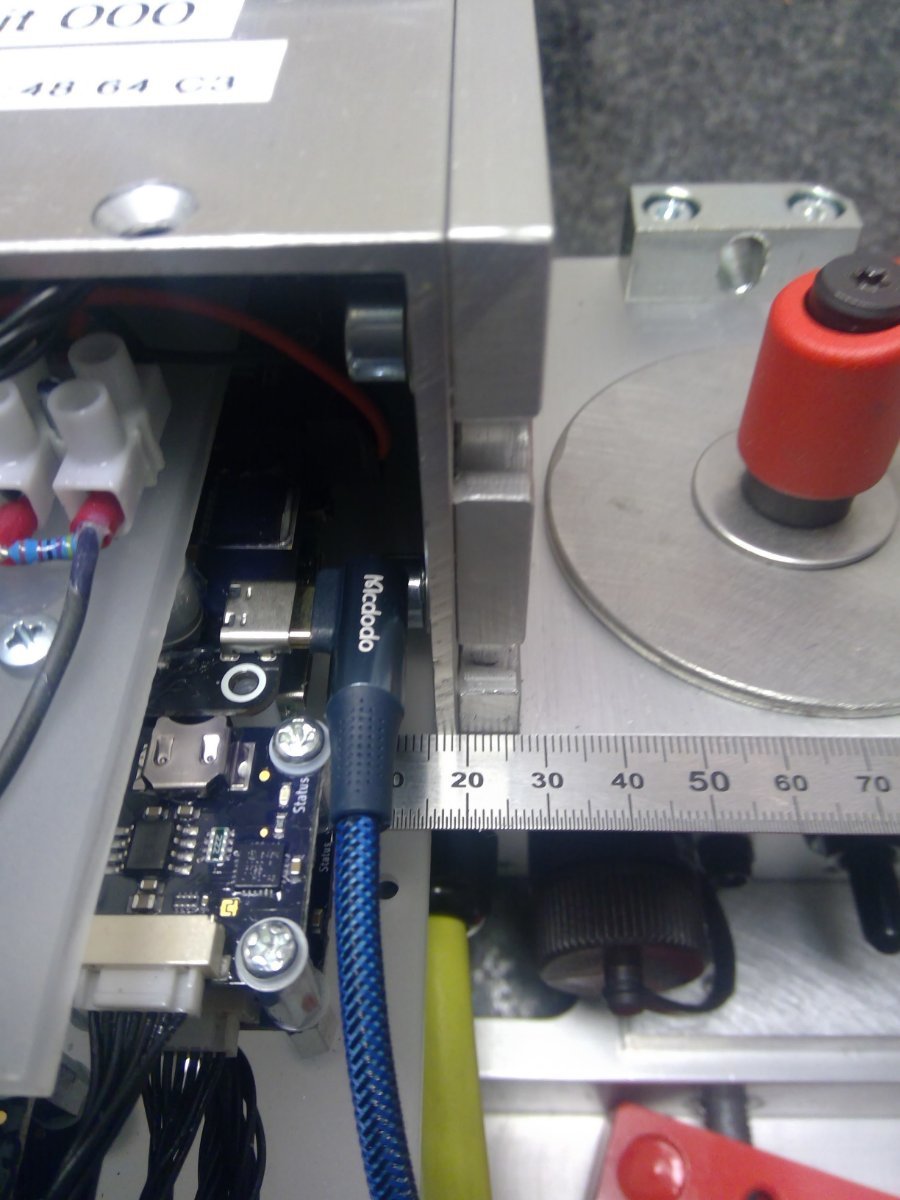
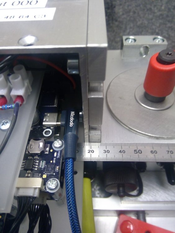
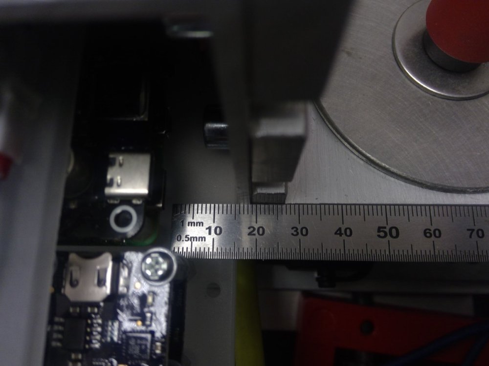
Dear batti Thank you very much for the advice and pointing out the precise location. I had a look at the HAT itself, puhh, this is all pretty small. I guess, this will exceed my skills of soldering 😟 I re-checked the available space between the USB-socket and the case were the RPI and the HAT are located: There are 15mm available. Using an USB-cable with a 90-degrees rotated plug, it should fit. See attached images. Probably, buying such cables, cutting and just using the two power-wires will be easier than soldering an additional cable onto the board of the HAT. Hope you agree. Cheers, Yvo
-
Hi Backdraft007 Perfect. Thank you very much. In this case, I will go with the positions of the bricklets. That sounds the most promising. Cheers, Yvo
-
Dear List I am using the Rugged Approach approach for programming in C# and in Python. It just works perfectly! Thanks for the great tutorial. Till now, I worked with many bricklets, but each of a different type. For this case, the approach and code in the tutorial works like a charm. Question: But what would be the best-practice, if you have several bricklets of the same type? Of course, I could use the UID of the individual bricklets to make the differentiation of the individual bricklets. But I would like to avoid the usage of the UID in Rugged Approach for several reasons: Lost of the very generic procedure of the Rugged Approach introducing somehow hard-coded UIDs of bricklet. Incompatibility of several installations of hardware having different UIDs. In the specific application I am working on, the bricklets are connected with a HAT Brick. Question: Is there a possibility to avoid the UIDs? Could I use the information of the ports were each of the bricklet is connected to? In this case, I have to make sure, that each bricklet is connected with a well defined port. An approach which could be realistic. The information of the port connected to would be based on the return value of the get_identity() function of each bricklet. If I would use the UIDs, is it reasonable/possible to change the UIDs of the individual bricklets to have the same UIDs of the bricklets in each identical installation of the hardware. Looking forward to any ideas and suggestions. Cheers, Yvo
-
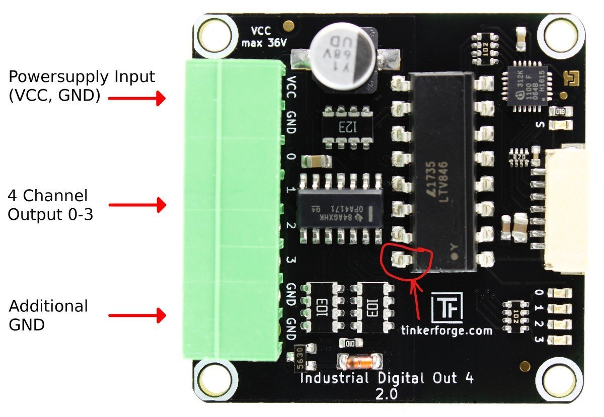
Dear List I have to use the 5V power-supply of the HAT Brick additionally to the 5-28V DC-input. But for constructive reasons (no available space), I cannot use an USB-connectors. Question: Is there a possibility / location to sold a cable directly onto the HAT Brick? With soldering directly a cable, I could use the additional power-supply (which I have to use for several reasons additionally to the 5-28V DC-input, see https://www.tinkerunity.org/topic/11345-hat-brick-und-strompi-3-mögliche-konflikte-bei-serieller-kommunikation-respektive-problem-bei-konfiguration-von-strompi-3/ ) even within the very small space available where the RPi and HAT are installed. Looking forward to any ideas and suggestions. Cheers, Yvo
-
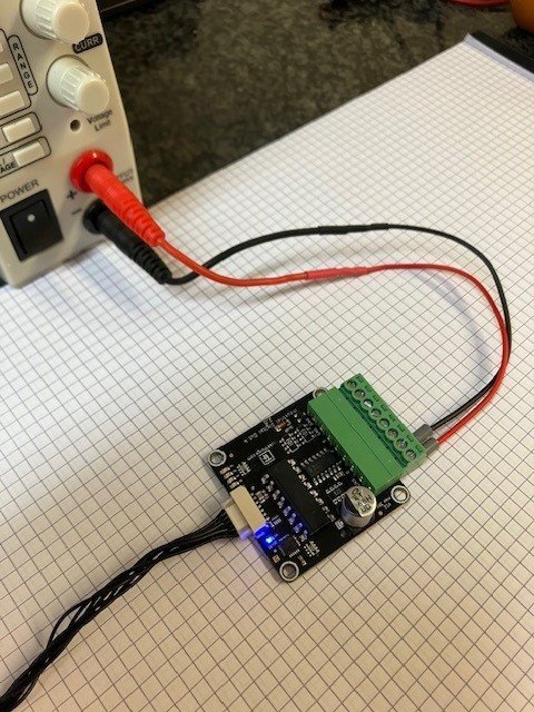
Das ist in der Tat sehr merkwürdig. Ich habe alles nochmals geprüft und vor allem die Pole des PowerSupply (siehe Foto). Da sehe ich keinen Fehler meines Erachtens. Oder mache ich etwas falsch?
-
Kein Problem. Ich bin leider ein Elektronik-Analphabet. Folgendes ist gemessen: In der blauen Verbindung messe ich in allen Schaltzuständen 24V (also wie PowerSupply).
-
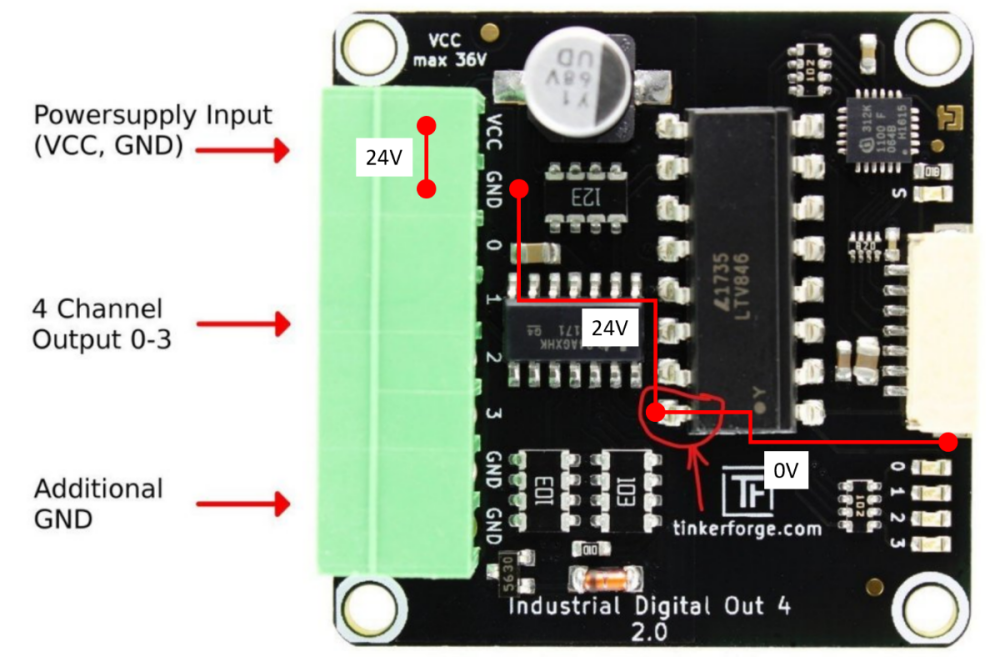
Salut MatzeTF Jetzt hoffe ich, dass ich Deine Frage richtig verstanden und umgesetzt habe. Skizze angehängt. Bricklet nur via 7Pin-Kabel am Master angeschlossen. Messung Spannung wenn nur via MasterBrick angeschlossen: 0V zwischen rot markiertem Pin und GND beim Anschluss Brick. Spannung von 24V am PowerSupply angelegt. 0V zwischen rot markiertem Pin und GND beim Anschluss Brick. 24V zwischen rot markiertem Pin und GND des PowerSupplys Bei beiden Schaltzuständen von Channel 0. Entspricht der Eingangsspannung am PowerSupply. War dies wie von Dir gewünscht gemessen? Mit den besten Grüssen, Yvo
-
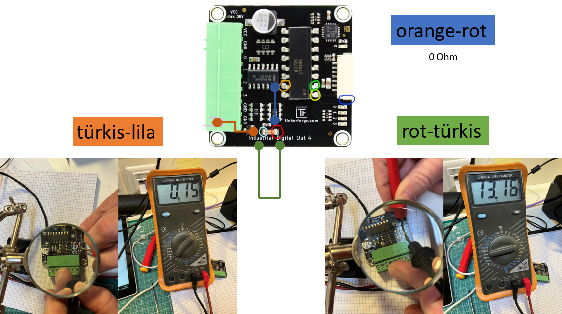
Salut MatzeTF Ich habe die verschiedenen Messungen gemacht: blau-gelb: In allen Zuständen eine Spannung von 3,3 V blau-grün: Bei Channel 0 auf GND -> 3.3V Bei Channel 0 auf VCC -> 2.2V Das sieht soweit sehr gut aus. Bei den Messungen der Widerstände muss ich Dir das angehängte Bild zukommen lassen. Da fehlt mir die Kenntnis dies zu interpretieren. Die Verbindung orange-rot gibt aber definitiv 0 Ohm. Hilft Dir das weiter? Mit den besten Grüssen, Yvo

-
Salut MatzeTF Vielen Dank für die schnelle Rückmeldung. Als Elektronik-Neuling habe ich versucht den Schaltplan und Deine Beschreibung zu interpretieren und am eingezeichneten Pin gemessen. An diesem Pin (wie auch an allen anderen) habe ich unabhängig von der VCC oder GND-Einstellung jeweils die Spannung vom PowerSupply gemessen. Komische Sache. Was meinst Du? Mit den besten Grüssen, Yvo

-
Hallo Liste Auf zwei Industrial Digital Out 2 (Version 2.0) Bricklets befinden sich die 4 Ausgänge immer im Zustand High. Auch wenn im brickv alle Ausgänge auf GND gesetzt sind. Wenn ich im Zustand GND im brickv die Spannung an einem Ausgang messe (zum Beispiel Channel 0 gemessen auf GND), messe ich die gleiche Spannung wie am PowerSupply (zum Beispiel 10V). Dies konsequent an allen 4 Ausgängen. Das Umschalten von VCC auf GND über Set Low und Set High macht keinen Unterschied. Nach meinem Verständnis, müsste ich bei GND eine Spannung von 0Volt messen und bei VCC eine Spannung welche identisch mit dem PowerSupply ist, oder? Frage: Habe ich in irgendeiner Art die beiden Industrial Digital Out 2 zerschossen? Oder mache, respektive überlege ich was falsch? Freue mich auf jeden Hinweis. Mit den besten Grüssen, Yvo
-
@Backdraft007 Ich habe mich ausführlich mit der von Dir angegebenen Webseite befasst. Und konnte zum Glück was herleiten, das für mich tauglich ist. Und ich habe noch das Glück, dass ich das Bricklet doch um 90 Grad drehen kann und die X-Achse nach "vorne" guckt. So kann ich mit dieser Achse anstelle der Y-Achse arbeiten. Die restliche Mathe um die Quaternionen musst ich leider aufgeben. Die Funktionen für die Berechnung der Rotation um die X-Achse im gewünschten Bereich von ]0, 2Pi[ sehen jetzt so aus: def normQ(q): ''' Calculates the normalized Quaternion a is the real part b, c, d are the complex elements ''' # Source: Buchholz, J. J. (2013). Vorlesungsmanuskript Regelungstechnik und Flugregler. # GRIN Verlag. Retrieved from http://www.grin.com/de/e-book/82818/regelungstechnik-und-flugregler # https://www.cbcity.de/tutorial-rotationsmatrix-und-quaternion-einfach-erklaert-in-din70000-zyx-konvention a, b, c, d = q # Absolute value used for the normalization. Z = np.sqrt(math.pow(a, 2) + math.pow(b, 2) + math.pow(c, 2) + math.pow(d, 2)) return np.array([a / Z, b / Z, c / Z, d / Z]) def Q2Eul(q): ''' Calculates the Euler Angles from Quaternion a is the real part b, c, d are the complex elements ''' # Source: Buchholz, J. J. (2013). Vorlesungsmanuskript Regelungstechnik und Flugregler. # GRIN Verlag. Retrieved from http://www.grin.com/de/e-book/82818/regelungstechnik-und-flugregler # https://www.cbcity.de/tutorial-rotationsmatrix-und-quaternion-einfach-erklaert-in-din70000-zyx-konvention ''' Getting the quaternion normalized. Remarks: * In case of Tinkerforge-IMU, the values given by the sensor have to be divided by 16383 (14 bit). * After the division, the values are already within the range ]-1, +1[. * Principally, no normalization requested. * To have a generic, function, the normalization of the quaternion is done in any case. ''' q = normQ(q) a, b, c, d = q z = np.arctan2(2.0 * (b * c + a * d), (math.pow(a, 2) + math.pow(b, 2) - math.pow(c, 2) - math.pow(d, 2))) y = np.arcsin(2.0 * (a * c - b * d)) x = np.arctan2(2.0 * (c * d + a * b), -1 * (math.pow(a, 2) - math.pow(b, 2) - math.pow(c, 2) + math.pow(d, 2))) * -1 x += math.pi return np.array([z, y, x]) def cb_all_data(acceleration, magnetic_field, angular_velocity, euler_angle, quaternion, linear_acceleration, gravity_vector, temperature, calibration_status): ''' Reduction of the values given by the sensor into the usual range of -1.0 to +1.0 for quaternions. Requested by the IMU-bricklet of Tinkerforge: * Division of the return values by 16383 (14 bit). ''' q = np.array( [quaternion[0] / 16383.0, quaternion[1] / 16383.0, quaternion[2] / 16383.0, quaternion[3] / 16383.0]) q2EulResult = Q2Eul(q) rotationX = q2EulResult[2] print("X-axis by quaternion (radians): " + str(round(rotationX, 2))) print("X-axis by quaternion (degrees): " + str(round(math.degrees(rotationX), 2))) So kriege ich aktuell die von mir benötigten Werte korrekt raus. Die Rotationen um die Y- und Z-Achse kann ich (zum Glück) ignorieren. Nochmals vielen Dank für den super Link. Mit den besten Grüssen, Yvo